Bede Aircraft was asked to develop a STOL aircraft of novel construction, while incorporating boundary layer control. They placed the design study with the Department of Aerodynamics at Maryland University. The boundary layer was controlled with a suction system via 160,0000 upper wing and aileron surface holes, with diameters ranging from 0.020 to 0.029 in (0.51 – 0.74 mm). Aluminium honeycombs were used throughout the fuselage as structural elements.
The XBD-2 was powered by a pair of flat-six piston engines mounted inside the fuselage, and used a single pusher configuration propeller, turning within a circular shroud. The wing of the XBD-2 had an aspect ratio of 9 and 5° of dihedral. It was built around an aluminium box spar, was aluminium skinned and carried sealed, all metal ailerons. A 14 in (356 mm) Joy blower pulled air through the pin-holes in the surfaces, venting it in the fuselage to cool the engines. Sealed flaps smoothly changed the wing camber and increased its area by about 15% when extended.
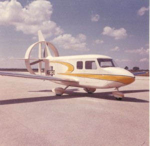
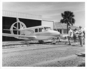
Apart from its use of aluminium honeycomb, the front part of the flat sided fuselage was conventional and used a cabin with enough space to seat four, though mostly filled with instrumentation. Two 145 hp (108 kW) Continental O-300 engines were mounted one above the other. They drove the rear propeller shaft through ten V-belts via Sprague clutches to avoid engine speed synchronisation problems. The rear fuselage tapered to a vertical wedge with the propeller shaft emerging at its top. The circular shroud was attached to the fuselage by the fixed triangular fin mounted on the top of the fuselage, the triangular tail plane and a short boom at the bottom. The propeller rotated close to the shroud’s leading edge; the shroud was intended partly to reduce propeller tip losses,but also to act in the place of conventional stabilizing surfaces. The fin resumed above the shroud and carried the top of a high aspect ratio rudder behind the shroud’s trailing edge, its bottom end attached to the tail boom and with a midpoint cut-out to allow for elevator movement. The elevator was supported by tail-plane extensions beyond the shroud, similar to that of the fin. Structurally, the shroud was a glass-fiber shell surrounding an aluminium spar and filled with polyurethane foam. The control surfaces were conventionally constructed from aluminium sheet.
The XBD-2 had a fixed tricycle undercarriage, with wheels enclosed in fairings. The main legs were glass-fiber cantilevers, which was unusual at the time. After the first XBD-2 flight on 26 July, 1961, it was flight tested and slightly modified to simplify future production.
It was intended to lead to the BD-3, which would have been a six seat airplane with bigger engines, use more honeycomb panels, use retracting undercarriage and have a laminar flow wing, but this was never built.
Crew: 1
Capacity: 4 total
Length: 23 ft 8 in (7.22 m)
Wingspan: 37 ft 6 in (11.42 m)
Height: 12 ft 5 in (3.78 m)
Wing area: 150.0 sq ft (13.94 m2)
Airfoil: Göttingen 549
Max takeoff weight: 3,300 lb (1,497 kg)
Powerplant: 2 × Continental O-300-A 6- cylinder horizontally
opposed air-cooled, 145 hp (108 kW) each
Maximum speed: 204 mph (328 km/h; 177 kn) at sea level
Cruise speed: 179 mph (156 kn; 288 km/h) maximum at 65% power at
9,000ft (2,740 m)
Stall speed: 42 mph (36 kn; 68 km/h) with BLC. Without BLC 64 mph
(57 kn;106 km/h)
Service ceiling: 21,000 ft (6,401 m) service
Rate of climb: 1,050 ft/min (5.3 m/s)
Take-off run: less than 300 ft (90 m)
Take-off distance to clear 50 ft (15.25 m): under 500 ft (152 m)
Landing distance from 50 ft (15.25 m): under 500 ft (152 m)